DIERS Benchmarks
Two-phase Flashing Flow case # 2 Download
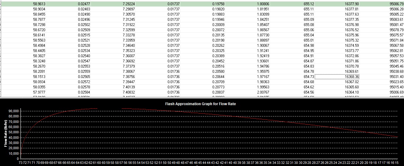
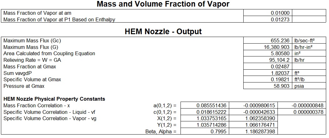
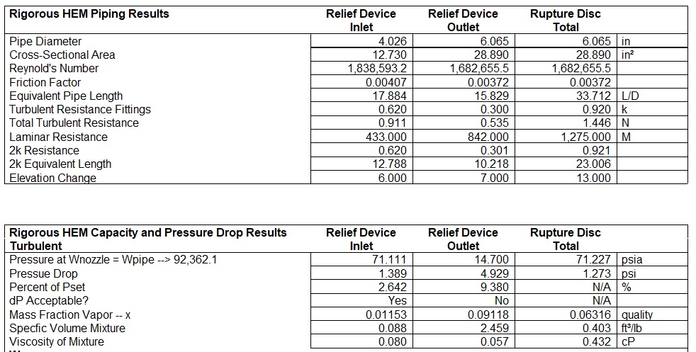
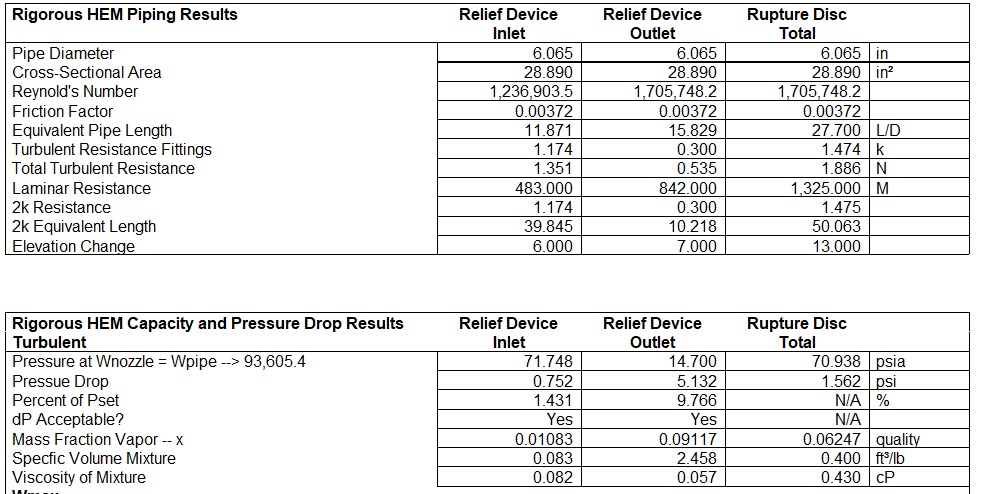
For the DIERS two-phase flashing flow a two-phase fluid (steam), at a relieving pressure of 72.5 psia and a quality of 0.01 is allowed to flash as it flows through the inlet pipe, entering the nozzle ( 4 P 6), and exiting through the discharge pipe. The Mach II uses the direct integration(HDI), of the VdP integral to calculate the maximum fluid flux(Gmax) through the relief nozzle which sets the basis for the relief design. Below you can view the results for the nozzle and you can view a snap shot of the direct integration table along with a graph showing the flow rate as a function of pressure. The flow reaches a maximum flux(Gmax) which can be seen from the integration table and also as the point of discontinuity on the graph.
Two-phase high viscosity Flashing Flow case # 4
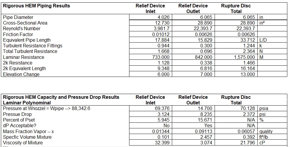
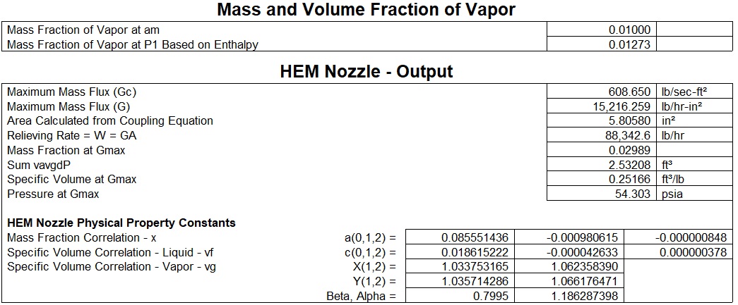
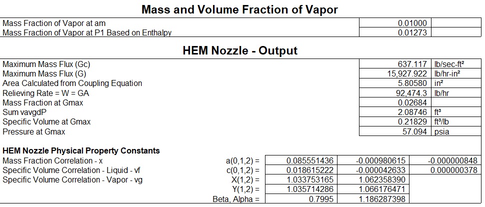
Next we will take the case of two-phase high viscosity flashing flow. The case will be the same as the above case #2 except that the viscosity will change as a function of temperature by the equation: µ = exp (A + B/ToK) . A = 2959.3 and B = -1.74.
Results Two-phase Flashing Flow
Flow rate (lbs/hr) Choke(psia) Quality inept dP / %Pset Outlet dP /%Pset Piping
95,104 58.9 0.0287 -------- ------- nozzle
92,362 56.8 0.0272 1.4 / 2.6 4.9 / 9.4 4 X 6
92,653 57.9 0.026 0.75 / 1.4 5.1/ 9.8 6 X 6
93,570 59.0 0.026 0.75 / 1.4 1.0 / 2.0 6 X 8
Results Two-phase High Viscosity Flashing Flow
95,104 58.9 0.025 --------- --------- nozzle
88,216 54.3 0.030 3.1 / 5.9 8.2 / 15.7 4 X 6
92,474 57.1 0.027 1.3 ? 2.5 9.0 17.1 6 X 6
