DIERS Benchmarks
Two-phase Flashing Flow
DIERS performed series of benchmark test on several relief calculations to include nozzles and piping.
There were 17 different relief cases that were investigated such as, vapor flow, two-phase flashing flow, hybrid flow, frozen flow, churn-turbulent, and bubbly flow. Within the categories of two-phase flashing flow, hybrid flow, and frozen flow were added low viscosity, medium viscosity, high viscosity, and very high viscosity cases.
The purpose of the benchmarks was to compare different computer programs results to determine consistency and identify errors or limitation of different methods. Several individuals participated in the benchmarks and their results were published in an article by Harold Fisher and Shawn P. Adair, entitled, "Benchmarking Two-phase Flow Through Safety Relief Valves and Pipe. Download
The physical property and vessel data for these cases are list below.
Vessel data
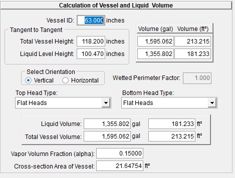
Volume 1595 gals.
Diameter 5.25 ft.
Height 9.85 ft. Initial fill ratio 0.85
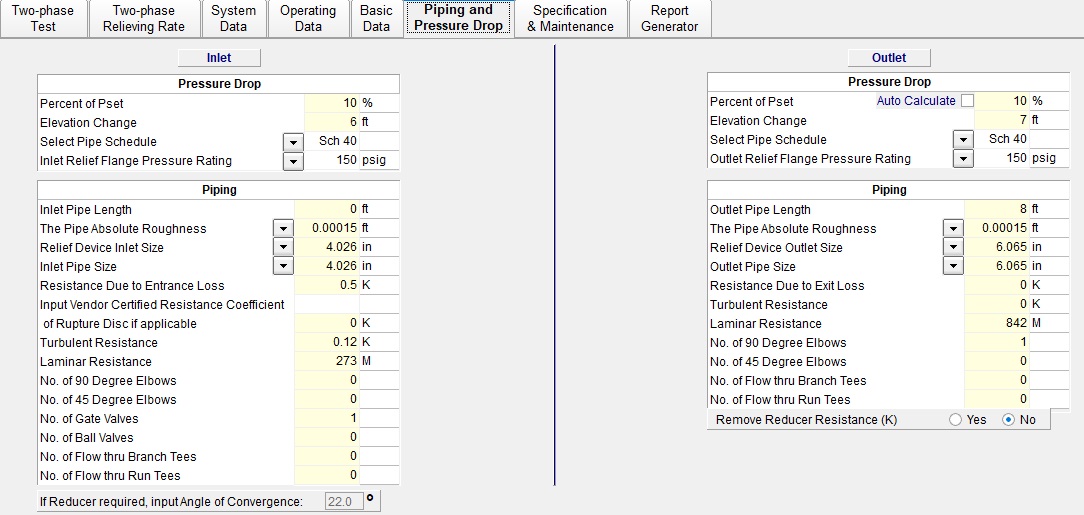
Relief valve 4 P 6
Orifice area 6.38 in2
Set Pressure 52.55 psig
Flowing Pressure 72.5 psia
Discharge coeff. (Kd) 0.91
Inlet line
Square cut entrance K = 0.5
internal diameter 4.026 in2
Horizontal length (0)
Vertical height 6.0 ft.
Full port valve K = 0.12
Discharge line
Intern diameter 6.065 in2
Horizontal length 1.0 ft.
St. 90 o elbow K= 0.30
Vertical height 7.0 feet
Physical Properties (from steam tables and physical property database or flash calculation)
Stagnation Ambient
Pressure (psia) 72.5 14.7
Temperature (oF) 304.5 212
X(quality) as specified
viscosity liquid (cp) 0.18 0.28
viscosity of gas (cp) 0.014 0.012
specific volume liquid(ft3/lb.) 0.01751 0.01672
specific volume of gas (ft3/lb) 6.0024 27.1
heat of vaporization(Btu/lb) 905.1 970.3
heat capacity(Btu/lb-0F) 1.0306 1.0056
heat capacity ratio 1.324


