Step 4-I
Two-phase Report
Inlet Piping
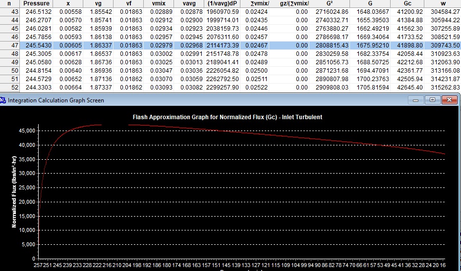
Examine the Mach II Two-phase inlet piping Report. The Mach II performs direct integration of the VdP integral to determine the required flux (G), that when multiplied by the cross-sectional area of the inlet pipe will match the same flowrate generated by the relief nozzle. The results are shown both numerically and graphically.
The Mach II takes the user input physical property data used for the nozzle, at three different pressure points to perform a regression analysis to generate pseudo-equations of state for the specific volume of vapor, the liquid and vapor viscosities, and the mass fraction as a function of pressure, so that these equations can be integrated over the pressure range to determine the mass flux as function of pressure as the fluid expands and/or flashes as it moves through the inlet piping.
These are the same equations of state that were used for the nozzle integration. This is because the relief nozzle and inlet piping operate along same pressie range. The fluid will expand and /or flash building momentum and velocity until it reaches a fluid flux (G) that gives a matching flowrate equal to the relief nozzle. At this point the fluid has reached equilibrium with the relief nozzle. The user can see both numerically and graphically how the fluid flux (G), and velocity will continue to increase until it reaches the equal flowrate of the relief nozzle.
As we review the results from the direct integration of the inlet piping, the pressure where Wpipe = Wnozzle , occurs at a pressure of 254.3 psia. The results are given below. However, even though the inlet piping can flow the rated nozzle capacity the pressure drop exceeds the required 3% of set pressure (Pset).
Examine the output report below the graph for the outlet piping results. For the outlet piping the user can see from the piping output report that the outlet pressure drop is within 10% of Pset, however the maximum flowrate of the outlet piping is less than the required flowrate based on the nozzle flowrate. The outlet flowrate shows only 72.095/7 lbs./hr. Therefore both the inlet and outlet piping must be increased to meet the required pressure drop and nozzle flworate.
The user will need to increase both the inlet and outlet piping and rerun the two-phase piping program.
Pressure where Wpipe = W nozzle 245.5 psia
Specific volume at choke 0.02979 ft3/lb
Mass flux at choke (Gmax) 41,899 lbs./in2 /hr
Flowrate 309,744 lbs/hr.
Pressure drop 4.35 % Pset
The inlet pipe size must be increased to minimize the inlet pressure drop below 3% of Pset to be in compliance with ASME Code.


