Step 4
Once the two-phase relieving capacity is determined then we will use DIERS methodology to determine the maximum fluid flux(Gmax) using direct integration of the VdP integral for the relief nozzle based on an article by Larry Simpson, "Estimating two-phase flow in Safety Devices", which will set the basis for the design of the relief orifice size using the equation, A = W/(Gmax), where A is the required orifice size, W is the two-phase relief rate, Gmax is the maximum fluid flux that typically occurs at sonic conditions.
This method will also be employed to determine the sizing of the inlet and outlet piping based on the Simpson article, " Navigating the two-phase Maze" We can then compare the two-phase relief orifice size with the existing single-phase orifice and piping size to determine if the existing relief device size and piping is adequate for both single and two-phase relief.
Step 4-B
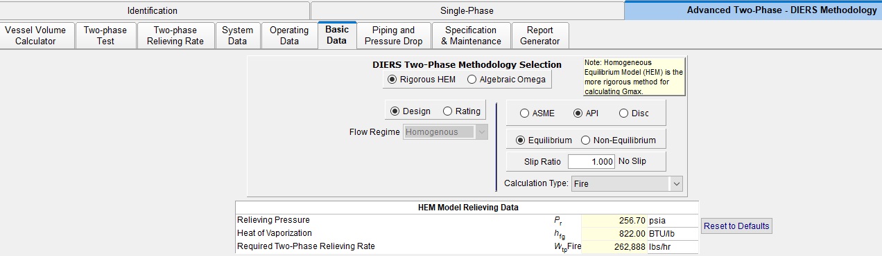
For the Main Basic Data" tab choose Rigorous HEM, for direct integration method, API sizing, Design mode, Equilibrium, and "1" for no slip between phases, to perform normal HEM calculation. Set calculation scenario type to "Fire" to transfer relieving pressure, heat of vaporization and the two-phase fire relieving rate from two-phase relieving rate tab.
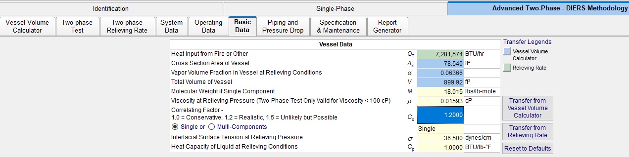
Step 4-C
For the Basic Data tab select "Vessel" from both right corner and then transfer the heat input from relieving rate tab, and the cross-sectional area, vapor volume fraction, and total volume from the vessel calculator tab, using the transfer buttons. Finally input the remaining physical properties, molecular weight, viscosity, interfacial surface tension, and heat capacity to complete the basic input data.