DIERS Methodology is used for the determination and sizing for two-phase flow in relief systems.
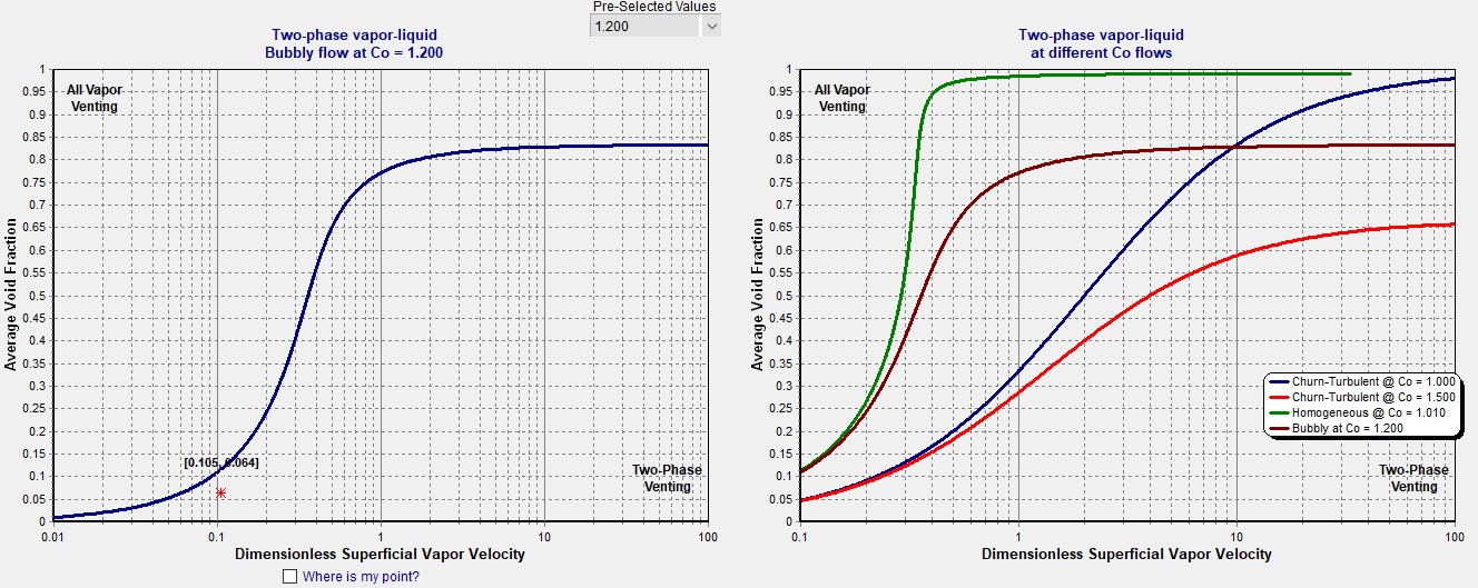
Above you see the (alpha) α vs. Ψ (Psi) curves that describe the type of relief venting that occurs based on the flow regime model. The alpha (α) represent the vessel void fraction (empty space) and the Psi (Ψ) represents the vapor superficial velocity in the vessel. The graph on the left is based on a fire case example and is determined to be bubbly flow, and the one on the right shows different flow regimes using different correlating factors. These two graphs show all vapor venting above the curve and two- phase venting below the curve. By the use of these curves, which are based on the vessel void fraction, and the superficial vapor velocity, DIERS methodology can determine the likelihood of two-phase flow relief venting by performing a two-phase test on the actual vessel venting conditions.
Once two-phase flow is identified then DIERS methodology is used to determine the two-phase venting requirements based on using different models such as the homogeneous two-phase fire case, bubbly and churn-turbulent fire case, runaway reaction, or other scenarios.
After the two-phase venting capacity is known, the designer must determine the maximum fluid flux (Gmax) to size the relief nozzle based on the simple equation, Area = Wtp/Gmax. DIERS methodology has several methods for determining the maximum fluid flux (Gmax) such as the one point Omega method, two-point Omega method (API method), Homogeneous Non-Equilibrium method (HNE), TPHEM model (CCPS), and the most rigorous method, Homogeneous direct integration method (HDI).
"Homogeneous Direct Integration(HDI), is universally applicable for all fluids under any conditions for which the property data are available. The procedure does not depend on whether the entering fluid is cold liquid, sub-cooled flashing liquid, a condensing vapor, or whether or not the flow is choked. It is simple to understand and apply, it is easily applicable to multi-component systems, can be applied too short, (non-equilibruim) (nozzle Length < 10 cm) as well as long (equilibrium) nozzles, and "Slip effects", can be readily incorporated." Reference article by Ron Darby, "Size Safety-Relief Valves for Any Condition".
The gas-liquid mass fraction leaving the vessel is defined by vapor-liquid onset-disengagement modeling. Most relief systems are designed based on the assumption of either no vapor-liquid disengagement (homogeneous), or complete disengagement (all vapor flow). The homogeneous assumption is the most conservative and is typically taken as the design basis for two-phase flow. However, in reality the homogeneous assumption can lead to over-sized relief devices and hence there is a need to model different flow regime models such as bubbly, viscous bubbly, churn-turbulent or others. By use of the DIERS coupling equation a relief design can be converted to other flow regime models that reflect more vapor-liquid disengagement than the more conservative homogeneous case. The two most widely used flow regime models are bubbly and churn-turbulent and both are incorporated into the Mach II software in addition to allowing the user to create his own flow regime model by modifying different variables. You can download the Mach II User and Training Manual to understand the two-phase design methodology. Download
WHAT IS DIERS METHODOLOGY?


